Some of you have been asking about the procedure for replacing the meter movements in portable instruments. Throughout the years, changes in technology have affected even the portable analog meter, with the upshot that what you need to do to replace the meter movement depends upon the vintage of the portable.
In early 1987, new portable instruments (beginning with serial number 46566) were fitted with a 1 mA meter movement instead of the 50 µA meter movement that had been used. Instruments prior to S/N 46566 can be retrofitted with a new 1 mA meter movement, provided the main circuit board has integrated circuits (ICs).
The 1 mA meter movement retrofit will not work in older portables that are fully-transistorized (that is, no ICs on the main circuit board). These fully-transistorized instruments have serial numbers less than approximately 9800. In this case, if a replacement is required, it should be done with the 50 µA meter movement.
Note: The 50 µA meter movement is still available as a replacement part (Part Number 15-8014). This must be specified when ordering a meter replacement.
Instructions for the modifications are described below. They are divided into 2 categories: electronic and mechanical. The serial number of the instrument to be modified will determine the extent of the changes required, as follows:
Instruments with serial numbers -
- less than approximately 9800 (fully transistorized) cannot be modified for the 1 mA meter movement.
- between approximately 9800 and 46566 require both electronic and mechanical changes.
- between 46566 and 69769 require only the mechanical changes.
- greater than 69769 normally require no change. See ** in note for item B1.
Instructions for Retrofitting the 1 mA Meter Movement in Instruments that Currently have a 50 µA Meter Movement (Model 3 used as an example)
A. Electronic - Resistor Replacement On Main Circuit Board
Note: Each portable model's main board layout is different, so these instructions will reference the resistors by function and by the Model 3 numbering system, as an example. Please contact us if you are unsure about your particular model.
- Replace the 22K ohm resistor on the output of the voltage follow with a 270 ohm resistor. In the Model 3, this is component R20.
- Replace the "select-at-test" (SAT) resistor for the "BAT TEST" function. For the Model 3, this is component R41. The value for this resistor will vary somewhat, in order to make the meter read properly, but it is probably 62K, as currently installed. Change it to a 2.2K ohm value, or something close to this value, as needed.
B. Mechanical Modifications - Spacers, Screws, Meter Back Post
- NOTE: This step only applies to instruments that have serial numbers less than 69769. After S/N 69769, the castings were changed to standardize the spacer size. ** However, if you find that the zero-adjust spiral roll pin is too short to engage the zero-adjust stem on the movement, a small spacer may be required and a longer screw. (LMI technicians use a 4-40 nut as a spacer.) If you do add a spacer, ensure that the meter needle moves freely and does not rub against the bezel glass.
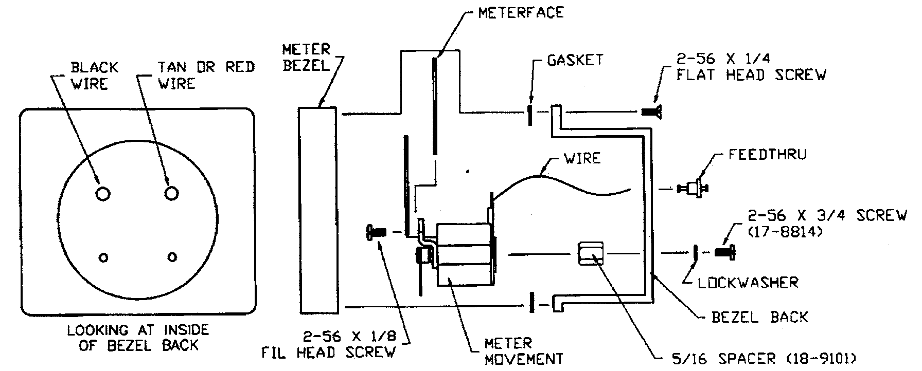
Refer to the diagram "Assembly Instructions for Meter Assembly 40-1805 (S/N less than 69769)" for screw and spacer sizes and locations. The 40-1805 assembly uses the new movement and fits castings prior to S/N 69769.
- All Model 19s: The post on the back of the new meter movement must be bent 90 degrees toward the meter face to clear the middle "feedthru".
Meter Assembly Part Numbers
| Item | Part Number |
|---|---|
| 1 mA Meter Kit (includes bezel with glass) | 4363-572 (for S/N > 69769) |
| 1 mA Meter Assembly | 40-1805 (for S/N < 69769) |
| 1 mA Meter Movement | 15-8030 |
| 50 µA Meter Assembly | 40-1802 (for S/N < 9800) |
| 50 µA Meter Assembly | 40-1801 (for S/N 9800 - 46566) |
| 50 µA Meter Assembly | 15-8014 |
By Beth Hall and Rollie Cantu, March & December 1997 Newsletters
