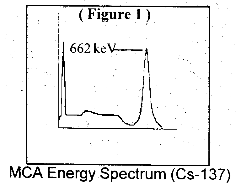
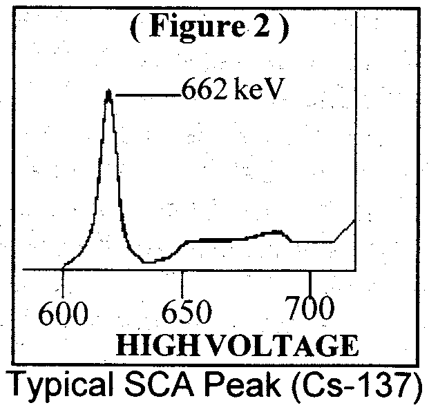
Single channel pulse height analyzer (SCA) energy calibrations can sometimes be confusing or even misleading if calibrated incorrectly. Unlike the MCA (multichannel analyzer), SCAs do not usually incorporate a monitor to display the radiation energy spectrum; therefore when calibrating (sometimes referred to as "peaking") a SCA and detector for a specific isotope photopeak, it helps to visualize the anticipated isotope energy spectrum (see figures 1 and 2). For discussion, we will use a Ludlum Model 2200 Scaler-Ratemeter/SCA and the Model 44-10 scintillation detector (2 in. x 2 in. NaI), but the same principle will also work for a proportional detector. Since 137Cs produces the most familiar energy spectrum, we will use it for the SCA peaking example.
The three adjustable parameters encountered on most SCAs are: the lower pulse height discrimination level referred to as the THRESHOLD (THR), the upper pulse height level referred to as the WINDOW (WIN), and the detector operating voltage referred to as HV (high voltage). The HV varies with the pulse amplitude from the detector. The THR and WIN adjustments establish the narrow counting window in which the pulses of interest are to be counted. The object of calibrating the SCA and the detector by varying the high voltage is to position the majority of the pulses of interest (photopeak) within the counting window.
Calibration Procedure
Determine the counting window width for the isotope. The THR and WIN controls on the Model 2200 utilize 10 turn dials which may be used to correlate directly to the energy level of the isotope. For 137Cs we will use a 40 keV counting window — the THR setting should be 642 and the WIN setting should be 040. Select the WIN "OFF" position to disable the upper pulse height level. Select the most sensitive ratemeter range (x1 for the Model 2200). Adjust the HV to approximately 450 volts. While observing the ratemeter, increase the HV until a sharp increase in count rate is observed with the source positioned near the detector and note the HV dial setting*. The point where the ratemeter starts to increase is the photo peak leading edge region (see Fig. 2). Switch the WIN "IN" and slowly increase the HV until the ratemeter starts to decrease and note the HV dial reading. This is the trailing edge of the photo peak illustrated in Fig. 2. Decrease the HV until the "peak" count rate is observed on the ratemeter. The HV dial reading should be near center between the two indications in the above previous steps.


*In studying the illustration in Fig. 2, it should be noted that if the HV is increased just a few increments beyond the point where the ratemeter just starts to respond, the photo peak can easily be passed up and the counting window could be centered on one of the backscatter peaks or possibly the 32 keV x-ray peak. Once the count rate starts, it may be more convenient to decrease the HV dial a few increments before switching the window "IN" to ensure that the photo peak is not passed up.
Some of the parameters that will affect the instrument response to the energy calibration are: the window width, the detector resolution, the activity of the radiation source, and the detector's efficiency to source activity.
