With the exception of the ionization chamber, most radiation detectors produce a current pulse for each detected incident. Most of theses pulses are small in amplitude which require amplification before the pulse(s) can be integrated for analog circuits or recognized by digital counting circuits. A single-ended, discrete amplifier made similar to the one below is used in the majority of Ludlum instruments to provide pulse amplification and inversion. This particular amplifier circuit is from the Ludlum Model 3. Before investigating some of the common problem symptoms and their solutions, a thorough understanding of the circuit theory should be reviewed.
Amplifier Circuit Review
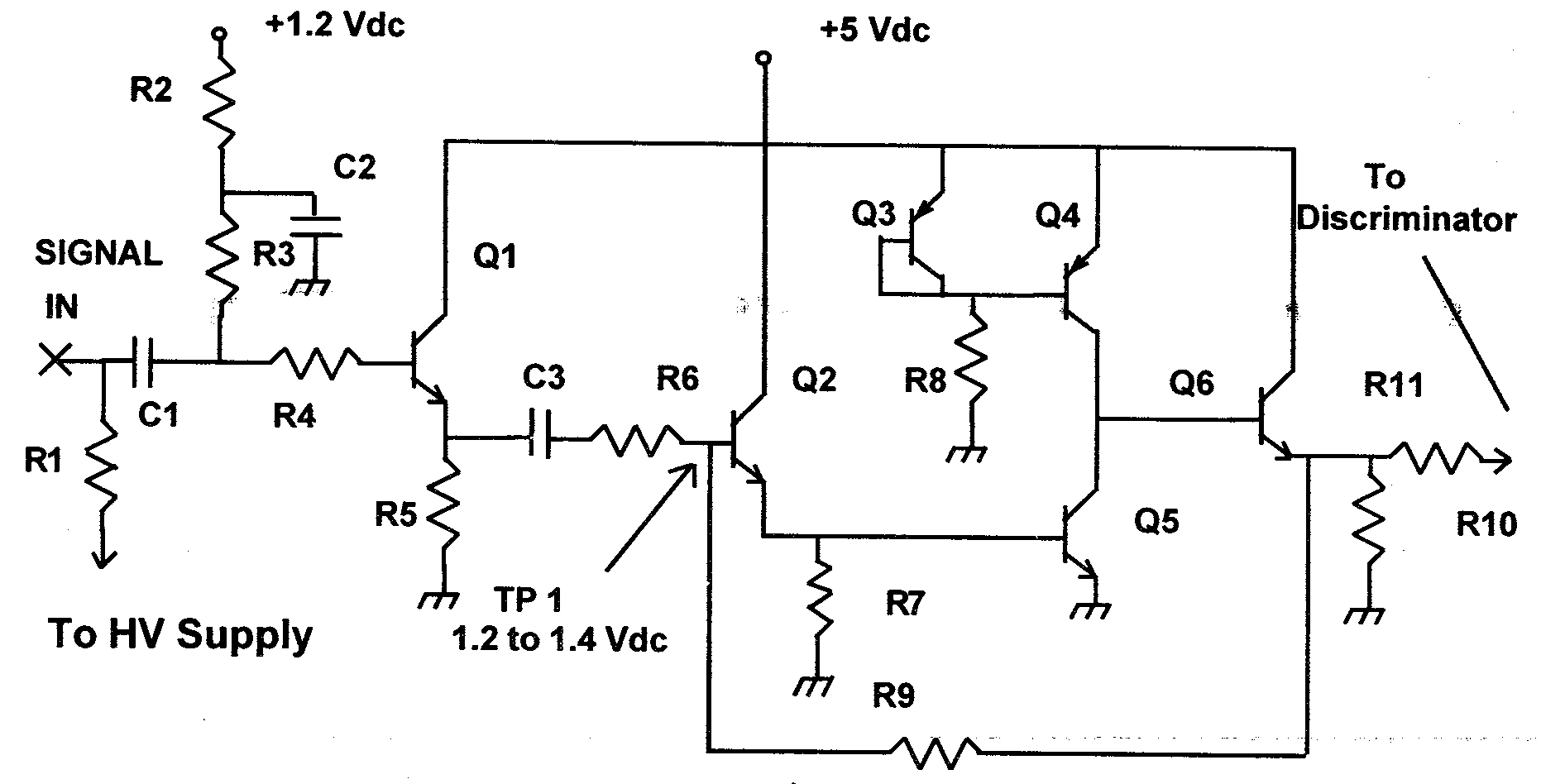
Negative going detector pulses are coupled from the detector through C1 to emitter follower, Q1. C1 is typically a 100 pF, 3kV capacitor which blocks the detector operating voltage (commonly referred to as high voltage or HV) and provides signal differentiation. R2 and R3 provide bias to Q1. R4 protects the input of Q1 from inadvertent shorts to the detector input connection. Q1 is configured as an emitter follower which provides a high impedance input for the signal. The self-biased amplifier, Q2 through Q6, provides gain in proportion to R9 divided by R6. Q5 provides amplification and signal inversion. Q3, R8, and Q4 are configured as a constant current source to the collector of Q5. Q2 and Q6 are configured as emitter followers which provide high input and low output impedances. The base of Q2 is biased at +1.2 to 1.4 Vdc via the emitter of Q6. Q5 conducts just enough current from the constant current source to hold the bias constant. Positive pulses at the emitter of Q6 are coupled to the discrimination circuitry via R11.
Problem Symptoms
The majority of the problem symptoms with a defective amplifier is that the input sensitivity (the threshold or discrimination point where the instrument responds to the pulse once it has reached a specific amplitude) has increased from the typical 25 to 35 millivolts to 4 or 5 volts or the instrument will not respond to a pulse input at all. These problems may occur when the detector input is inadvertently shorted while the HV is up — instrument left on when connecting or disconnecting the detector — or a problem has occurred in the HV regulation circuit allowing the HV to increase rapidly, shorting or opening one of the amplifier transistor junctions. The primary technique in troubleshooting the amplifier circuit is the required transistor base to emitter bias voltage. The transistors are silicon type which require 0.6 to 0.7 volts between the base and emitter junctions for collector to emitter conduction. Therefore when these transistors are biased and working correctly, a voltage drop of 0.6 to 0.7 Vdc should be present between the base and emitter leads. This is why TP1 requires 1.2 to 1.4 Vdc, because half of this voltage is dropped across the base and emitter of Q2 and the other half across the base and emitter of Q5. Since the 1.2 to 1.4 bias is produced by Q6 then the base of Q6 should be the emitter of Q6 plus 0.6 to 0.7 thus equaling approximately 2 Vdc. The base of Q1 will be approximately 1.2 Vdc with the emitter at 0.6 Vdc.
Problem Scenario
The instrument and detector will not respond to a radiation check source and the problem has been isolated to the instrument by substituting a known good detector or connecting a pulse generator to the instrument. The bias voltage at the base of Q1 is approximately 1.2 Vdc and the emitter is 0.6 Vdc so Q1 appears to be working properly. but when the bias is measured at TP1, 3.5 to 4 Vdc is measured instead of the required 1.2 to 1.4 Vdc. This measurement would indicate that Q2 has opened causing Q5 to shut off. This allows the collector of Q4 to increase near the supply voltage producing a higher voltage at the emitter of Q6 and the base of Q2.
Summary
Even though some variations of the amplifier circuit illustrated in this article will be encountered, the primary features will be the same — pulse amplification and inversion is produced by the amplifier and the proper vias voltage is required for transistor conduction. Please contact LMI for additional technical support in isolating and repairing LMI instruments.
By David Wyatt, March 1996 Newsletter